

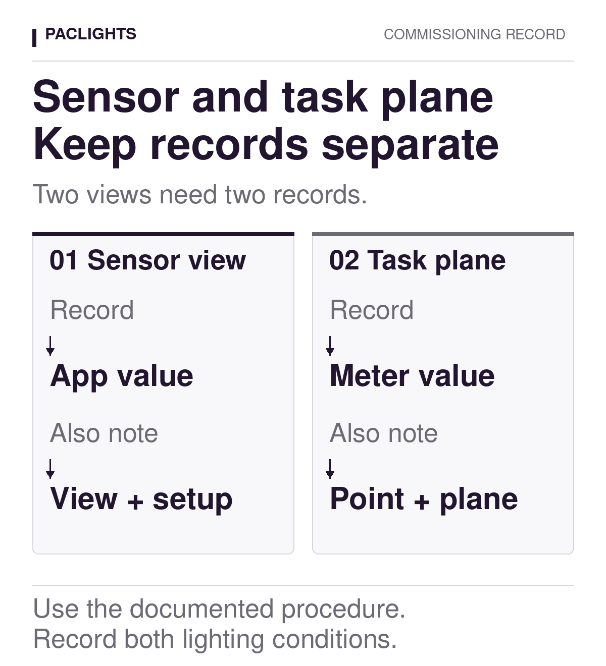
A daylight-control commissioning record should keep two observations separate: the signal or value reported by the installed photosensor, and illuminance measured at a defined task-plane location. They describe different views of the space. A ceiling sensor responds to light within its field of view and according to its own control logic; a meter at a work surface records light incident at that point. One value should not be presented as the other unless the selected system’s documented commissioning method explicitly establishes that relationship.
This distinction matters when a control appears to dim correctly while a workstation, rack face, or other task location still raises a question. It also matters when an app displays a convenient number that looks like a light level. The commissioning team needs a record that shows what was observed, where it was observed, and what the electric lighting was doing at the same time.
Start with the meaning of each reading
Before comparing numbers, identify the control method and the source of every displayed value. Record the photosensor model or control option, its installed position, the zone or fixtures it commands, and whether the reported value is a raw sensor signal, a calculated daylight value, a percentage, a setpoint, or another manufacturer-defined quantity. Do not rename an unfamiliar app value as “lux” or “foot-candles” because it changes when the light changes.
Then identify the task-plane observation separately. State the surface or task being assessed, the exact measurement location, the plane orientation, and the meter orientation. A horizontal reading on a workbench and a vertical reading on a rack face answer different questions. A floor reading is not automatically a substitute for either one.
PacLights’ guide to daylight-control sequences explains why switching, stepped dimming, continuous dimming, and dim-to-off must be specified as operating behaviors. The measurement record builds on that decision. It does not replace the approved sequence or create a universal calibration target.
Choose task-plane locations that represent the design question
A useful reference point is tied to a real visual task and to the project’s design documents. It might represent a workstation near glazing, an interior work surface farther from daylight, a packing bench, or another location named in the lighting plan. The point should be repeatable, not a convenient spot chosen during the test.
Mark each location on a plan or a photograph and give it a stable identifier. Record height, orientation, and nearby features that can affect the reading. If several points matter, keep them as separate rows rather than averaging them into one undocumented “room level.” The purpose is to preserve the spatial difference that the photosensor may not see.
Keep the list focused. A commissioning record is not a substitute for a complete photometric survey. Use the design team’s defined assessment locations and criteria, and flag missing or ambiguous locations for clarification. If the design question concerns a task surface, do not move the point to the floor simply because the floor is easier to reach.
Document what the photosensor can see
The sensor’s field of view is part of the evidence. Record its location and orientation, then note the surfaces and light sources that dominate that view. Skylights, windows, ceiling finishes, high racks, partitions, stored material, bright work surfaces, and electric luminaires can all change the signal reaching a ceiling-mounted device.
Photographs are useful when they are labeled and dated. Take one view that establishes the sensor location and another that shows representative surroundings without implying a precise coverage cone. A manufacturer diagram may describe intended positioning, but it does not document the actual finished space.
Finishes and shading deserve their own fields. Record whether blinds or shades are open, closed, or at a documented position. Note whether reflective temporary material, uninstalled furnishings, open dock doors, or changing rack loads are present. These details help explain why the same sensor value may not correspond to the same light at a task point on another day.
Separate daylight contribution from electric-light state
A task-plane meter sees the combined result of daylight and electric light unless the procedure deliberately isolates them. The record should therefore state the operating condition of the controlled fixtures at the time of each observation. Identify whether they are off, at a documented standby level, at full output, or responding automatically. Also note schedules, occupancy commands, manual overrides, and neighboring zones that may be contributing light.
If the approved method calls for separate observations, label them clearly. For example, one row may capture the task-plane reading under the documented daylight condition with the controlled electric lighting off; another may capture the combined condition at a stated control output. Do not subtract readings or infer a daylight contribution unless the measurement method and operating states support that calculation.
The parking-garage sensor walk-test guide makes the same practical point for occupancy response: a useful test starts from a known state and records other active commands. Daylight commissioning needs the same discipline. A control demonstration is difficult to interpret when the starting condition is missing.
Use a repeatable observation record
A compact log can connect the observations without collapsing them into one number. Include the following fields for each test interval:
- Time and daylight condition: date, time, sky or shading condition, and any meaningful change during the observation.
- Sensor record: sensor ID, displayed value and units exactly as shown, enabled function, zone assignment, and relevant settings.
- Task-plane record: point ID, surface, height, orientation, meter ID, and observed illuminance with units.
- Electric-light state: commanded state, observed output condition, active schedule or override, and response of adjacent zones.
- Space condition: shades, finishes, furnishings, racks, open doors, temporary obstructions, and other factors that change either view.
- Disposition: accepted observation, discrepancy to investigate, responsible party, and repeat-test reference.
Write observations before diagnoses. “Task point T-3 measured differently while the sensor displayed the same manufacturer-defined value” is useful evidence. “Bad sensor” is not. The first statement preserves the two observations and gives the project team a basis for reviewing placement, zoning, settings, surface conditions, or the selected control method.
Repeat under documented conditions, not improvised ones
Follow the current procedure for the installed sensor and controller. Some systems use a guided calibration process; others rely on a setpoint or a relationship entered during commissioning. The method may differ for open-loop and closed-loop arrangements, and product-specific algorithms can affect what an app or controller reports.
When repeating a check, preserve as many conditions as practical: the same point, plane, meter orientation, shading state, fixture state, and zone commands. If conditions cannot be reproduced, record the difference rather than presenting the two readings as a direct comparison. Rapidly changing daylight may make a long sequence of measurements difficult to compare; note the limitation and use the project’s approved procedure for timing or stabilization.
Do not improvise by covering a sensor, shining a flashlight at it, or changing several settings at once and then treating the result as normal operation. A temporary test mode can be useful when the manufacturer supports it, but the record should identify that mode and include the required return to normal settings.
Check the complete fixture and control configuration
The control option belongs to a specific fixture, driver, sensor, and interface combination. PacLights’ FLHE linear high bay is controls-ready and offers distinct occupancy, daylight-harvesting, and networked-control options. That product-family description is a starting point, not proof that every configuration has the same commissioning steps or reported values.
Use the actual ordering record and current product documentation for the supplied configuration. Record the control option, relevant software or firmware identifier when the manufacturer procedure requires it, and the document revision used for commissioning. If a displayed value cannot be interpreted from that documentation, send the exact question to the appropriate manufacturer or controls specialist instead of assigning a meaning from appearance alone.
Leave a record the facility team can reuse
Handover should preserve the zone plan, sensor and fixture identities, task-plane point map, observation log, final settings, exceptions, and the manufacturer procedure used. The lighting-controls handover guide shows how to connect fixture records, zone assignments, settings, tests, and later changes without overwriting the original baseline.
That baseline is especially valuable after partitions, shades, racks, furnishings, fixtures, or controls change. The next commissioning provider can repeat the relevant observations and distinguish a changed sensor view from a changed task-plane condition. For a PacLights project review, bring the fixture and control schedule, the plan with reference points, the current settings record, photographs of the installed conditions, and the specific discrepancy. Those materials turn a vague complaint into a traceable technical question.
Disclaimer: PacLights is not responsible for any actions taken based on the suggestions and information provided in this article, and readers should consult local building and electrical codes for proper guidance.