

Recheck a warehouse lighting layout whenever a rack change alters the path between a luminaire and the work people need to see. Taller racks, narrower aisles, new cross-aisles, different picking levels and relocated staging areas can all make an existing calculation less representative. The fixtures may still work correctly while the lighting no longer serves the revised arrangement.
Start with a documented comparison of the old and proposed racks. Then ask the lighting designer to evaluate the affected areas using the actual installed equipment and revised geometry. Keeping every high bay, moving selected fixtures or changing optics should follow that review. A rack move alone does not establish which option is appropriate.
Record the change before deciding what to move
A useful change record begins with two drawings that share a coordinate reference: the last verified arrangement and the proposed arrangement. Mark rack rows, aisle edges, cross-aisles, columns, doors, staging positions and fixed equipment. Give each affected row a stable identifier so that the warehouse team, contractor and lighting designer can discuss the same location.
Include rack height, shelf or beam elevations, aisle width and the planned storage envelope. The highest permitted load may extend beyond a beam, so a drawing of empty racking can understate the obstruction. Record whether shelving is open, solid or fitted with a deck, and identify large loads that interrupt light reaching lower positions. Use observed conditions or agreed operating limits rather than guessing at a typical load.
Describe the task as carefully as the geometry. Floor-level travel, reading a vertical location label, picking from a shelf and checking paperwork at a bench are different visual tasks. A revised layout may change the task even where the racks stay at the same height. Note the normal viewing direction and where a worker or vehicle is likely to block the light.
Separate floor lighting from rack-face and task checks
A floor calculation describes illumination on its specified horizontal plane. It does not, by itself, establish how well a vertical label or recessed picking location is illuminated. Ask the designer to identify the calculation surfaces that represent the revised work: the floor or travel plane, relevant rack faces and any separate work surfaces.
Keep the acceptance criteria attached to each surface. The project team should agree on the applicable illuminance and uniformity requirements for the task, including whether results are initial or maintained. Do not transfer a target from an unrelated warehouse or assume that a single average describes every aisle. A higher average can coexist with weak locations at aisle ends or behind obstructions.
Compare like-for-like calculation grids when reviewing the old and new arrangements. If one report covers an open floor and the other includes narrow rack aisles, their summary values may describe different conditions. Ask for drawing revisions, grid extents, plane heights, obstruction assumptions and light-loss assumptions to be identified in the report. Record limitations where detailed shelf modelling is outside the calculation scope.
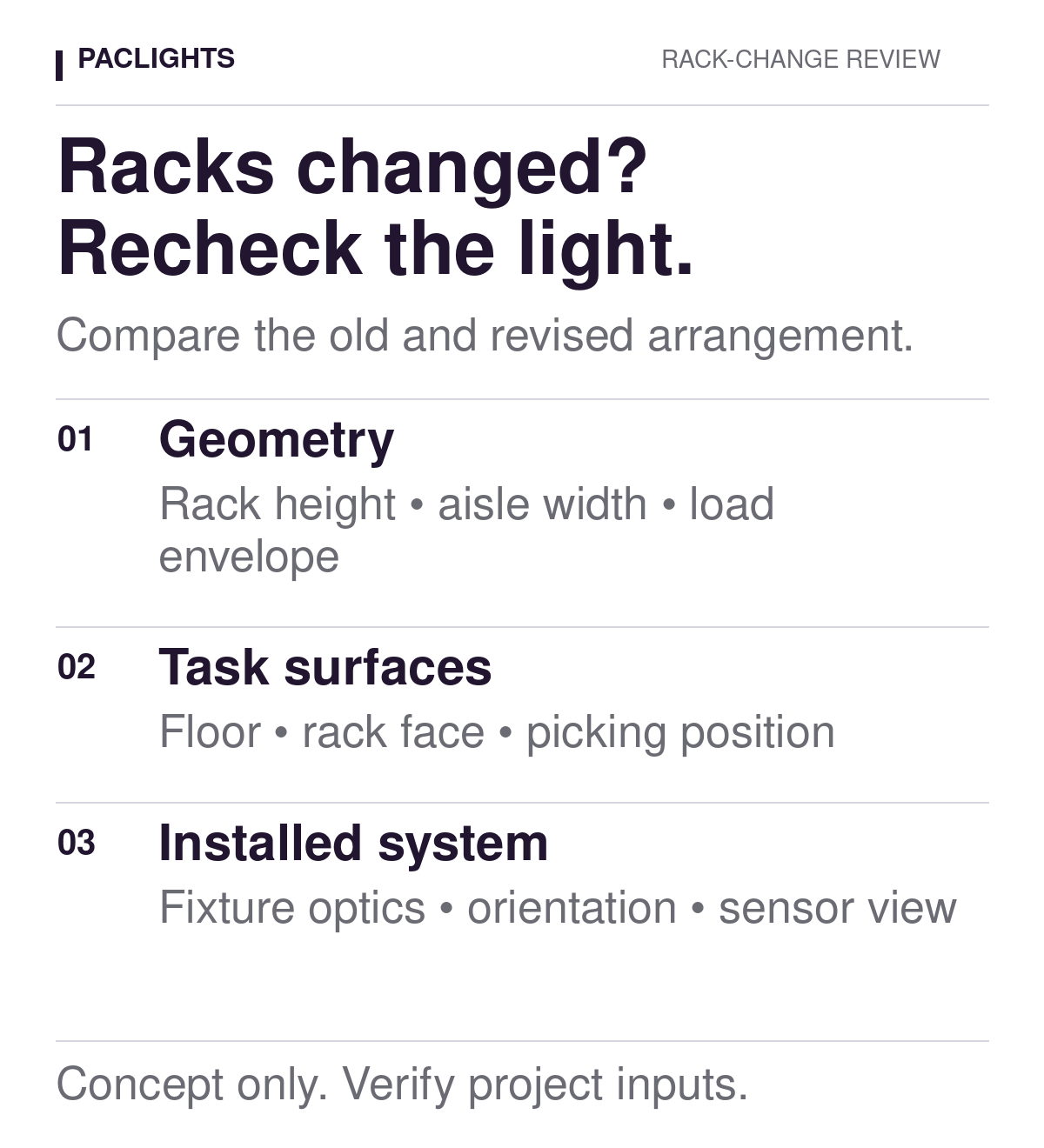
Match installed fixture locations and optics to the new aisles
Overlay the existing luminaire positions on the revised rack drawing. A fixture that was centered over an aisle can end up above a rack or close to its edge after reconfiguration. Check the luminaire’s mounting elevation and orientation as well as its plan position. The relevant distance to a raised picking surface differs from the distance to the floor.
Confirm the actual fixture and optical option from equipment records or a safe inspection. A family name and a nominal lumen package are not enough to identify the intensity distribution used in a calculation. Request the corresponding IES photometric file and confirm its relationship to the installed variant. Where an aisle optic is used, verify its intended orientation against the new aisle direction and the manufacturer’s documentation.
The PacLights FLHE linear high-bay family lists optional aisle optics and several control choices. Those options make the installed configuration relevant to a rack-change review; they do not mean every FLHE installation has the same optics or sensors. Confirm the exact option before making a reuse decision.
For a wider discussion of positioning, task lighting and warehouse zones, see our warehouse lighting layout guide. For a rack revision, base the decision on the revised project calculation rather than adopting a general spacing example as a design rule.
Request a comparison that answers a specific decision
Give the designer a clear question: can the existing arrangement serve the revised racks, and where does it need adjustment? Start with the actual installed positions and equipment. If that arrangement does not satisfy the agreed criteria, compare a defined alternative, such as relocating selected fixtures or evaluating another documented optical configuration.
Keep other assumptions consistent between alternatives unless the change is intentional and explained. Record fixture output settings, photometric files, mounting positions, surface assumptions, light-loss factors and calculation areas. Otherwise, an apparent improvement may come from a changed input rather than from the proposed physical arrangement.
Consider a conceptual example: one rack row becomes taller and the adjacent picking aisle narrows. Even if the fixture count and ceiling height remain unchanged, the load envelope, fixture-to-aisle relationship and vertical picking surfaces have changed. That combination warrants review. It does not establish how many fixtures must move or what light levels will result. Those conclusions require the project inputs and calculation.
Where the review points toward a broader equipment upgrade, our warehouse retrofit planning overview provides background on coordinating fixtures, controls and project phases. Develop any savings estimate separately from verified wattage, operating hours and the proposed control sequence; a rack drawing is not an energy model.
Recheck sensor views and control-group boundaries
Racks affect control operation as well as light distribution. Taller storage, a closed shelf deck or a relocated load may obstruct a sensor’s view. A new cross-aisle can introduce an approach from a direction that was not part of the original test. Review the actual sensor type, installation position and manufacturer guidance rather than assuming every sensor responds alike.
Compare the intended occupied area with the fixtures assigned to its control group. A group that matched the previous aisle may now span unrelated tasks or leave an approach route outside the intended response. Check the approved sequence, standby level, delays, daylight interaction and overrides as applicable to the installed system. Record settings with units and retain their previous values before authorized adjustments.
After the physical work is complete, test representative approach routes and working positions under controlled conditions. Record the initial lighting state, the first observed response, which fixtures respond and what happens after activity stops. Keep people and vehicles under the facility’s normal work controls during testing. An observed response at one convenient point does not verify an entire aisle.
Close the change with a usable record
Keep a short closeout file containing the approved rack drawing, equipment and optics schedule, calculation report, control-group record and site observations. Identify what was verified, what remains uncertain and who owns each outstanding action. Preserve the drawing and report revision so a later rack move does not begin from an obsolete baseline.
Use the revised drawing during the site walk. Confirm that the installed racks, load limits and fixture positions match the reviewed arrangement. Investigate discrepancies before accepting results that depend on a different geometry. Where measurements are required, use the agreed planes, grid and operating conditions, and distinguish measured observations from calculated predictions.
To begin a PacLights project review, assemble the before-and-after rack drawings, mounting heights, fixture and control schedule, available IES files, and the tasks that have changed. Identify the affected rows and the decision you need to make. That information gives the review a practical endpoint: a documented basis for retaining, relocating or revising the lighting around the new racks.
Disclaimer: PacLights is not responsible for any actions taken based on the suggestions and information provided in this article, and readers should consult local building and electrical codes for proper guidance.