

A parking garage sensor test should follow the routes people and vehicles actually use, starting with the lights in their normal unoccupied state. Check where the intended fixtures respond, whether the response follows the route, and how the zone returns to standby after activity stops. Waving beneath one sensor answers only a small part of that test.
A useful walk test turns a complaint such as “the lights come on too late” into a location, a starting condition, and an observed result. That gives the installer or controls specialist something specific to investigate. It also gives the facility team a repeatable way to check the installation after settings or site conditions change.
Agree on the expected response first
Before entering the garage, review the approved sequence of operation and the fixture and control schedule. Identify the occupied output, unoccupied or standby output, relevant timing settings, daylight response, and any scheduled or manual overrides. Where fixtures operate as a group, identify exactly which fixtures each sensor should command.
Write the acceptance condition in terms of the route. For example: the designated pedestrian-zone fixtures should reach their specified occupied state before a person reaches a marked checkpoint. The project team must choose that checkpoint and the required response; neither is a universal factory setting.
Keep this functional check separate from verifying illumination. A fixture can respond promptly while the installed layout still needs attention. Use the project’s defined measurement locations and lighting criteria for the separate illuminance assessment. Required emergency and egress lighting functions belong to their approved design and testing procedures.
Mark routes, obstructions, and zone boundaries
Use a simple plan showing driving aisles, parking bays, columns, ramps, lobby doors, and pedestrian paths. Add fixture IDs, sensor positions, and control-zone boundaries. Mark the places where a person or vehicle first enters a monitored area, passes an obstruction, or moves into the next zone.
Include approaches that are easy to miss during a demonstration: someone leaving a parked vehicle, a driver rounding a column, and a pedestrian returning from the lobby. Test both directions where both occur in normal use. A successful approach from one direction does not establish coverage from every approach.
Use the sensor manufacturer’s coverage information for the actual mounting arrangement. A coverage circle on a submittal does not reproduce the installed effect of beams, columns, or parked vehicles. Document representative conditions rather than relying on an empty garage as the only test condition.
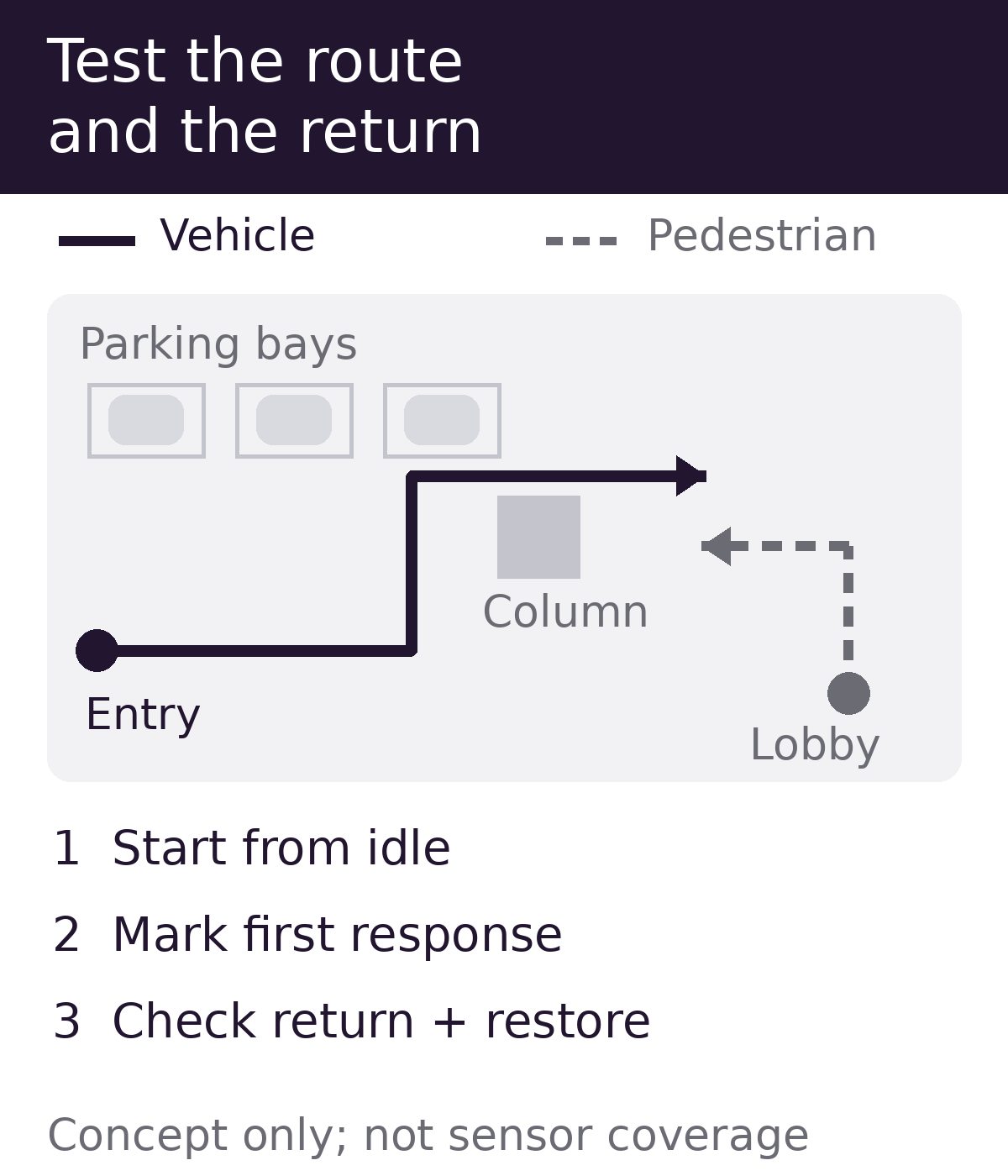
Start from the normal unoccupied state
Let the zone complete its normal timing sequence before the first approach. Record whether the lights are at standby, off, or another intended state. An observer standing within the detection area, activity in a linked zone, or an active override can prevent the expected starting condition.
If the lights remain at occupied output, establish why before judging the sensor. Review the active schedule, daylight conditions, group commands, and other movement. Record the time and conditions so a later comparison has meaning.
Use manufacturer-supported test modes when useful, but identify them on the record. An accelerated test can help locate a detection boundary; it does not verify the normal hold or standby timing. Restore the operating settings and repeat the relevant checks before accepting the zone.
Walk the pedestrian approaches before the vehicle pass
Coordinate testing with the operator and keep pedestrians clear of moving vehicles. Start on a designated pedestrian route at an ordinary walking pace. Do not enter an inadequately illuminated area simply to prove that a sensor is late; stop and arrange controlled testing.
Record the point where the first intended fixture responds, which fixtures respond with it, and whether the next section follows the approved sequence. A group that brightens behind the walker may be a zoning or coverage issue even though individual sensors are detecting movement.
Repeat the approach from the lobby and from representative parking bays. Note any change associated with a column, beam, or parked vehicle. Keep the route and initial conditions consistent while comparing results; changing the path and several settings together makes the cause harder to isolate.
Check the driving route under controlled conditions
Arrange a separate vehicle pass with a designated driver and a safely positioned observer. Follow the operator’s traffic plan and posted rules. The driver should concentrate on driving; the observer records the lighting response.
Check the entry, turns, ramp approaches, and transitions between control zones. Observe whether the intended area ahead responds at the agreed checkpoint, rather than noting only that a fixture somewhere switched on. Record conditions that affect interpretation, including daylight at an open perimeter and existing vehicle activity.
Consider an illustrative corner beside a lift lobby. A pedestrian approaches from the door and the first luminaire brightens, but the next section remains at standby. If local tests show both fixtures respond individually, check the group assignment and command sequence; increasing sensitivity alone may not address that observation. If neither fixture responds along that approach, review the sensing geometry and enabled functions before treating it as a communications issue. These checks narrow the investigation; they are not a diagnosis from one pass.
For a garage with networked controls, separate two observations: the local fixture’s response and the response of its assigned group. Detection at one fixture does not establish that the group is assigned or configured correctly. PacLights’ wireless lighting controls guide provides background on grouping and configuration.
Stay for the return to standby
After activity leaves the zone, observe the full return sequence. Record the last observed movement and the subsequent changes in output. Distinguish the time at occupied output from any later period at a standby level. If an off state is specified, check it separately from dimming to a low level.
Then repeat an approach from that low or off state and verify restoration. A zone that dims successfully but does not recover as intended has not completed the functional test.
Where daylight control is enabled, record whether it is influencing the result. Do not disable it and present the test as proof of normal combined operation. Test the required conditions using the manufacturer’s procedure. PacLights’ daylight-control sequence guide explains why daylight switching, dimming, and restoration need explicit definitions.
Check the supplied fixture and control combination
Work from the as-built equipment record. PacLights’ FCPG parking garage lights include optional motion, daylight, and networked control configurations. The FCPG/3 specification distinguishes PIR and microwave control options. Record the installed option rather than assuming the fixture family identifies its sensing behavior.
For a project using FVTB vapor-tight lights, the current generation also offers integral sensor and wireless-control options. Verify the exact configuration and its instructions before adjusting settings. Similar-looking fixtures or shared control terminology do not establish interchangeable settings, detection patterns, or commissioning procedures.
Leave a test record someone can repeat
Use one record per route and starting condition. Include the date, tester, zone and fixture IDs, sensor option, current settings, daylight conditions, route direction, and relevant obstructions. Mark the first observed response and any missed or unexpected fixture on the plan.
The following blank structure is a practical starting point:
| Record | What to enter |
|---|---|
| Route and starting state | Route ID, direction, occupied/standby/off state, and active commands. |
| Expected response | Checkpoint, designated fixtures, output state, and timing from the approved sequence. |
| Observed result | First response location, fixtures affected, return sequence, and restoration. |
| Follow-up | Specific adjustment or investigation, responsible person, and repeat-test result. |
Write observations before diagnoses. “Zone B stayed at standby when approached from the lobby” is more useful than “bad sensor.” A late response calls for checking coverage, placement, sensitivity, and control priorities. An incorrect group response calls for checking assignments and communications. Change one relevant variable at a time, within the manufacturer’s instructions, and repeat the same route.
Handover should include the marked plan, final settings, test records, and unresolved exceptions. Retest affected routes after changes to fixtures, controls, partitions, or parking arrangements. For a PacLights project review, bring the fixture and control schedule, mounting information, route plan, and recorded results. Those details make the discussion about the actual operating problem rather than a generic request for more sensitivity.
Disclaimer: PacLights is not responsible for any actions taken based on the suggestions and information provided in this article, and readers should consult local building and electrical codes for proper guidance.