

A light-trespass review becomes actionable when the designer can identify the real boundary, the neighboring locations that may receive or view the light, and the exact lighting arrangement being evaluated. A note such as “light reaches the next property” does not define where to calculate, which direction a receiving plane should face, or which operating condition created the concern.
Start by building a project input package rather than selecting a shield or changing an aim by trial and error. The package should connect current site geometry, receptor locations, fixture configuration and operating modes to the applicable project criteria. That lets the designer test a specific condition, document revisions and avoid treating one accessory or one generic limit as a universal solution.
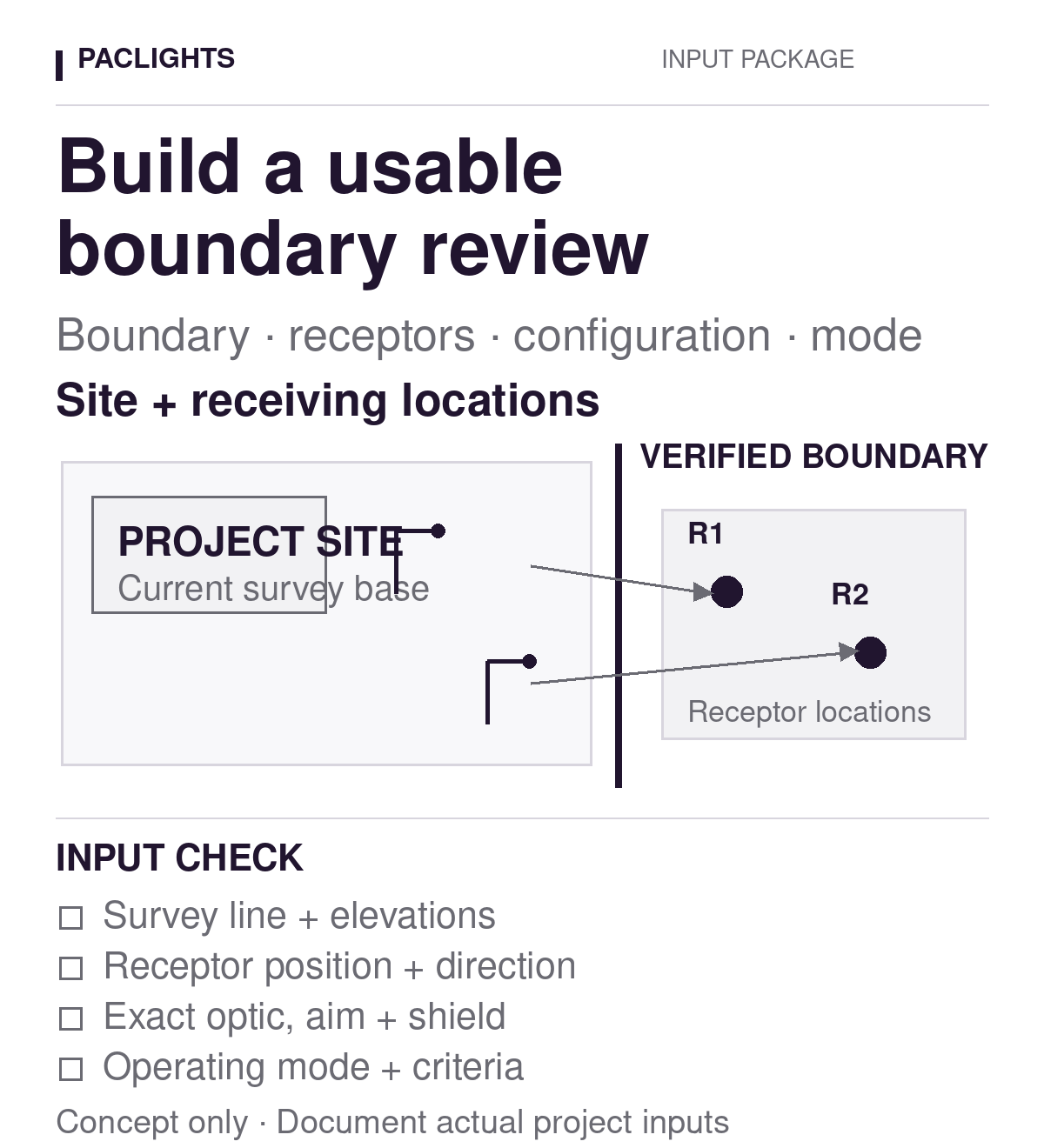
Establish the boundary before placing calculation points
Use a current survey, civil drawing or other project-controlled source to show the relevant property line. A curb, fence, landscape strip or edge of pavement may be visually convenient, but it is not automatically the legal or review boundary. If a right-of-way, easement or shared drive affects the question, mark it separately and ask the responsible project professional which line governs the review.
Give the designer a drawing reference and revision, not a screenshot with an unverified line drawn over an aerial image. Show the site coordinate system or dimensions needed to relate the lighting plan to the boundary. Where the ground changes elevation, provide the grades or spot elevations needed to locate the calculation plane in three dimensions.
Do not assume every point along a long boundary has the same significance. Identify the section related to the concern while preserving enough surrounding context to understand nearby poles, buildings, trees and circulation. A calculation can include a defined series of points along that section without implying that a single reading represents the entire perimeter.
Locate the neighboring receptors, not just the property line
A boundary illuminance check and a glare review answer different questions. Spill illumination concerns light arriving outside the intended area. Glare concerns the view of a bright source and depends on where the observer is located and looking. Skyglow involves upward light and reflected light. The project may need to consider more than one of these effects, so the input package should not collapse them into one unlabeled “light pollution” value.
Mark the relevant receiving locations: a facing window, property entrance, sidewalk, roadway approach or other project-defined receptor. Record horizontal position and elevation. If a window is above the project grade, its height matters. If the receptor is a moving observer on a public way, define the review positions and directions with the designer rather than choosing the most dramatic photograph.
For a spill-light calculation, state the receiving-plane orientation that the project method requires. A vertical plane facing the site is not equivalent to a horizontal ground plane. For a source-visibility or glare question, provide the observer position, eye height if required by the method, and the viewing direction. These are design inputs, not universal instructions; the applicable ordinance, approved criteria or responsible professional should define the actual method.
Record the exact luminaire and optical arrangement
A family name and wattage rarely describe the complete photometric configuration. Record the model generation, lumen or wattage selection, color setting where relevant, optical distribution, mounting type, mounting height, tilt, rotation and accessories. Tie each unit to a stable pole or building identifier and the current fixture schedule.
The PacLights FALC area-light family lists Type III as standard and Type II, IV and V distributions as options. Those choices illustrate why a calculation should use the IES file for the ordered configuration, not a convenient file from the same family. Confirm the selected wattage, distribution and control options against current project records.
The PacLights FFHL flood-light family lists multiple beam choices and an optional glare shield. A shield may change source visibility or distribution, but its presence alone does not demonstrate that a boundary or glare criterion is met. Ask whether the calculation represents the installed shield and its documented orientation.
Provide the actual IES photometric file used for the proposed or installed configuration, plus the product data and approved submittal that establish the match. Note any field-selectable setting and how it was confirmed. If a luminaire was substituted, preserve the earlier assignment and record the approved change rather than quietly replacing the model name.
Describe orientation and mounting without ambiguity
For area lights, confirm that the drawing’s orientation convention matches the photometric file and the installed luminaire. A plan arrow needs a defined reference; “facing north” can still be ambiguous if the housing, pole arm and photometric forward direction are not related. For floodlights, record the aiming method and reference convention rather than estimating tilt from a ground-level photograph.
Include pole coordinates, mounting heights and arm lengths where they affect the model. For wall-mounted equipment, show the building face, mounting elevation and setback from the boundary. Record obstructions or reflective surfaces that the designer needs to represent. Existing vegetation can be noted, but a tree should not automatically be treated as permanent photometric control without project direction.
Photographs are useful when each image is tied to a fixture ID, location and viewing direction. Capture enough context to show the relationship between the luminaire, boundary and receptor. A close-up of a bright source may document visibility, but camera exposure and automatic processing do not turn the photograph into a calibrated glare or illuminance measurement.
Separate the operating modes being reviewed
State when the concern occurs and which luminaires are on. Record the scheduled scene, dimming level, photocell state, occupancy response and any curfew or after-hours condition that applies to the project. If a control system groups several poles, identify the group and the command used during the review. Do not mix readings or observations from different states without labeling them.
A useful design comparison may include the normal occupied condition and a defined reduced-output condition. Both should use the same site geometry and clearly identified equipment settings. The comparison does not authorize a new sequence; it helps the project team evaluate the approved operating modes. Verify that any proposed change still supports the required lighting task and applicable safety criteria.
Controls also affect field verification. A luminaire that changes output while measurements are collected can invalidate a comparison. Coordinate a stable authorized test condition, record its start and end time, and note ambient or daylight conditions that could affect the observation. Restore normal operation in accordance with the site’s procedure.
State the governing criteria and the review question
Provide the ordinance section, permit condition, approved lighting criteria or other project reference that applies, including its revision or adoption date. Do not paste a numerical limit from a different jurisdiction or another project’s report. Criteria can vary by land use, lighting zone, time period, receiving plane and receptor type; the designer needs the one that governs this site.
Phrase the requested review precisely. Examples include checking calculated vertical illuminance along a defined property-line segment, evaluating source visibility from identified windows, or comparing two authorized operating modes. If the issue combines spill illumination and glare, ask for separately labeled results. A clear question helps the reviewer select the correct calculation and output rather than returning a broad rendering that does not resolve the concern.
The parking-lot lighting planning guide provides broader layout context. For a boundary review, retain the narrower record of property geometry, receptor directions and exact equipment configuration. General pole-spacing examples or broad light-level discussions cannot replace that project-specific package.
Request a documented calculation review
Ask the designer to identify the software and calculation file revision, luminaire photometric files, calculation planes, point spacing, surface assumptions and operating state. Results should show which criteria were checked and where. Keep calculated spill illuminance, glare-related outputs and skyglow considerations distinct, with the limitations of each method visible.
Track revisions through a short change log: what input changed, who authorized it, which model revision incorporated it and what result was reviewed. If a fixture moves, an optic changes or a receptor elevation is corrected, preserve the earlier result and issue a new calculation rather than overwriting the record. This makes a later field comparison traceable.
The sports-lighting aiming-schedule review explains the same document-control principle for fixture assignments and aiming references. Boundary reviews benefit from that discipline even when the site uses area lights rather than sports lighting.
Field observations can then be compared with the approved model under a defined method. Record the meter, plane, orientation, location, units and operating conditions. A difference should trigger investigation of geometry, equipment settings, obstructions, calibration and model assumptions; it is not by itself proof that one product or accessory failed.
Send a complete input package
A practical submission includes the current survey or civil base, relevant elevations, receptor markers, fixture and control schedules, exact photometric files, mounting and orientation records, photographs, operating modes, governing criteria and the specific review question. Identify unresolved assumptions instead of filling them with convenient defaults.
For a PacLights project discussion, gather that package with the current submittals and the designer’s latest calculation revision. The goal is not a generic promise of zero spill light. It is a documented review of the actual boundary, receptors, equipment and operating conditions, with each revision traceable to a project decision.
Disclaimer: PacLights is not responsible for any actions taken based on the suggestions and information provided in this article, and readers should consult local building and electrical codes for proper guidance.