

Getting wafer installation depth wrong in drop ceilings costs time and money. Poor placement leads to thermal issues, uneven light distribution, and fixtures that don’t perform as rated.
We at PacLights have seen countless installations fail because installers skip the depth calculation step. This guide walks you through the exact measurements and techniques that work.
What Makes Wafer Downlights Different and Why Installation Depth Matters
The Slim Profile Advantage
Wafer downlights are the slim, recessed fixtures that sit nearly flush with your drop ceiling tiles. Unlike traditional can lights that protrude 6 to 8 inches into the plenum space, wafer lights typically measure just 1 to 2 inches deep, making them the go-to choice when clearance is tight. The typical gap between a structural ceiling and a drop ceiling runs only 4 to 12 inches, which means standard housings simply won’t fit. Wafer downlights solve this problem by delivering recessed aesthetics without the depth penalty. They’re LED-based, generate minimal heat, and mount directly into the grid or the tile itself. This shallow profile is exactly why contractors reach for wafers on retrofit projects and new builds where plenum space is scarce.
How Depth Controls Performance
The real advantage isn’t just the compact size-it’s that wafers distribute light evenly across a room without the glare and hot spots that deeper fixtures often create. Installation depth directly controls thermal performance, light output, and how long the fixture lasts. When you install a wafer too shallow, you trap heat against the ceiling tile and risk burning out the LED driver in under a year. Install it too deep, and you waste precious plenum space while creating mounting headaches. The sweet spot depends on your specific fixture model, the insulation above the grid, and whether your tiles can handle the weight.
Four Critical Installation Mistakes
Most installers mess up depth by guessing instead of measuring. They assume all wafers install the same way or skip checking the fixture’s thermal rating and insulation contact requirements. ENERGY STAR-certified LED fixtures typically require at least 3 to 4 inches of clearance above the fixture for airflow, yet many people cram them tight against the structural ceiling and watch them fail. Another common error is ignoring the grid’s load capacity.
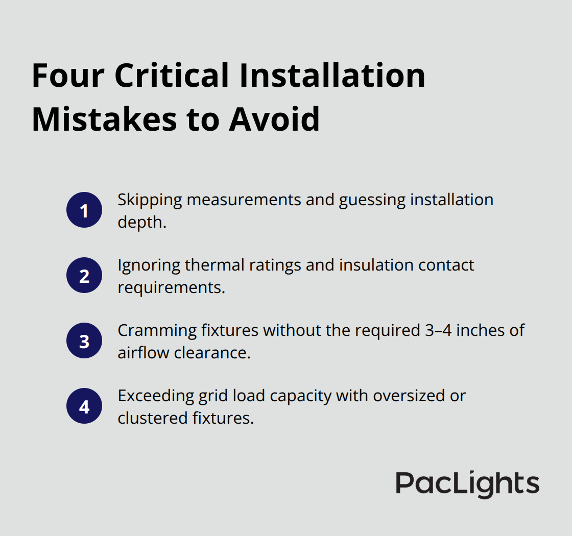
Drop ceiling grids are designed to carry roughly 2 to 3 pounds per square foot, and oversized or poorly distributed fixtures exceed that limit, causing sagging and misalignment.
A third mistake is failing to account for ceiling tile material. Some tiles are flimsy and need reinforcement clips or mounting bars to support even a 2-pound fixture. If you install without these supports, the tile bends, the fixture sits crooked, and light distribution becomes uneven. The fourth pitfall is mixing fixture depths across the same space. If half your wafers sit flush with the tile and the other half sit 2 inches deeper, the room looks disjointed and performs inconsistently.
What Proper Installation Requires
Proper depth installation requires a photometric layout, accurate measurements, and compliance with your fixture’s rated specifications. This isn’t optional-it’s the foundation of an installation that performs, lasts, and looks professional. Understanding these depth requirements sets you up to move forward with confidence. The next section walks you through the exact measurements and calculations that work for different fixture types and ceiling configurations.
What Depth Works for Different Wafer Types
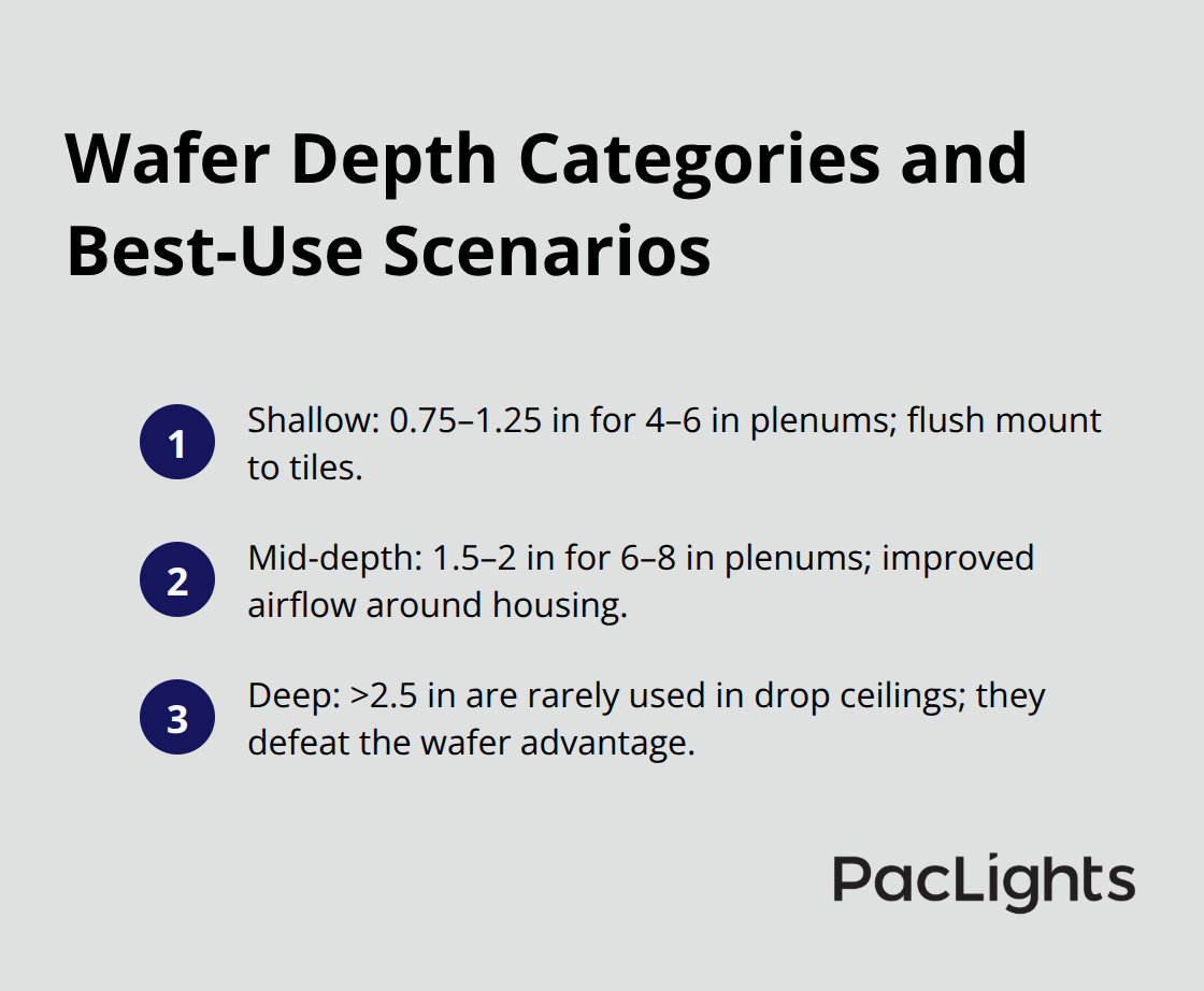
Wafer downlight depth varies by fixture design, and knowing your specific model’s requirements prevents costly installation errors. Most LED wafer lights measure between 0.75 and 2.5 inches deep, but this narrow range hides critical differences. Shallow wafers rated at 0.75 to 1.25 inches work best in plenums with 4 to 6 inches of clearance and mount directly flush with ceiling tiles. Mid-depth wafers at 1.5 to 2 inches fit standard 6 to 8-inch plenum spaces and offer more robust thermal management because they sit slightly recessed into the grid frame, allowing airflow around the housing. Deep wafers exceeding 2.5 inches are rare in drop ceiling applications because they defeat the purpose of choosing wafers over traditional can lights.
Specification Sheets Tell You What You Need to Know
Your fixture’s specification sheet lists the exact depth, thermal requirements, and insulation contact rating. IC-rated fixtures tolerate direct contact with insulation above the grid, while non-IC models need 3 to 4 inches of clearance for heat dissipation. ENERGY STAR certification requires this clearance, and ignoring it voids the warranty and creates fire risk. Measure the space between your structural ceiling and drop grid first. If you have only 4 inches of clearance, you must choose fixtures rated for that depth and verify they’re non-IC or IC-rated depending on whether insulation sits directly above. If you have 8 to 12 inches, you have flexibility across wafer types, but tighter isn’t always better. Cramming a fixture into minimal space creates thermal stress even if it physically fits.
Plenum Conditions Drive Your Installation Depth
Plenum conditions dictate whether you can install at the shallow end or need extra depth for safety. Insulation placed directly above the grid requires IC-rated fixtures, and these typically need at least 1.5 to 2 inches of depth to accommodate the thermal rating and maintain safe operating temperatures. If insulation sits loosely above the grid or doesn’t contact the fixture at all, non-IC wafers work fine at shallower depths. Grid load capacity matters equally. A standard drop ceiling grid handles 2 to 3 pounds per square foot distributed across the tiles. A single wafer weighs 1 to 3 pounds depending on the model, and adding multiple fixtures in one area creates concentrated load points.
Weight Distribution and Grid Reinforcement
Space your fixtures at least 4 to 6 feet apart horizontally to distribute weight evenly across the grid. If your layout clusters fixtures close together, reinforce the grid with supplemental mounting bars or angle iron to prevent sagging. Ceiling tile composition also affects depth decisions. Fiberglass tiles flex more than mineral fiber, and flimsy tiles need reinforcement clips or mounting brackets to support even lightweight fixtures. Measure and calculate before cutting holes. Use the fixture’s template to mark locations, then verify alignment with a laser level. Mark the ceiling grid layout on a scaled floor plan and count how many fixtures you install per grid section. If a 2 by 2-foot section holds more than one fixture, that section exceeds safe load distribution and needs bracing. This calculation takes 10 minutes and prevents callbacks.
Moving Forward with Confidence
Once you’ve confirmed your plenum clearance, identified your fixture’s depth rating, and verified that your grid can handle the load, you’re ready to select the exact wafer model that fits your space. The next section walks you through the specific measurements and calculations that ensure your chosen fixtures perform at rated specifications and last for years without thermal or structural issues.
Installing Wafer Downlights the Right Way
Plan Your Layout Before You Cut
Start with a laser level and a ceiling diagram before you touch a single tool. Mark your fixture locations on the grid using chalk or a pencil, then verify spacing with the laser to confirm every hole sits exactly where your photometric layout specifies. Most installers rush this step and end up with crooked rows that look unprofessional and distribute light unevenly. Use the fixture’s template as your cutting guide, tape it to the ceiling tile, and trace the outline with a marker. Cut slowly with a drywall saw or hole saw sized exactly to the template specifications. Oversized holes let fixtures tilt, undersized holes force you to enlarge them later and waste time.
Run Electrical Circuits and Secure Connections
A licensed electrician must run the wiring before you install housings. Separate circuits for different zones allow you to control lighting independently across the space. Junction boxes sit within the plenum and must remain accessible for future maintenance. Secure the electrical connections with wire nuts rated for the gauge you’re using, then tape them with electrical tape to prevent vibration-induced loosening. This preparation prevents callbacks and ensures code compliance.
Mount Fixtures Flush and Test Alignment
Mount the fixture housing using the grid-compatible brackets supplied by the manufacturer. Most wafers use spring clips that grab the grid frame, but some require supplemental mounting bars if your grid is weak or if multiple fixtures concentrate weight in one area. Test the fit before you fully secure anything. The housing should sit flush with the tile surface with zero gaps around the edges. If gaps exist, the tile is warped or your hole is misaligned. Adjust the mounting brackets or trim the tile edge carefully until the fixture sits perfectly flush. Install the LED module and trim ring last, after all structural mounting is complete. This prevents damage during installation and lets you verify alignment before final assembly.
Verify Performance and Thermal Output
Test each fixture immediately after installation while you’re still on the ladder. Power on the circuit and confirm that light output is even across the beam pattern and that there’s no flickering or buzzing. Flickering indicates a wiring issue or a defective driver that needs replacement before you move forward. Check the fixture’s surface temperature with an infrared thermometer after 10 minutes of operation. Wafer downlights should run between 50 and 65 degrees Celsius under normal conditions. Temperatures exceeding 70 degrees Celsius signal inadequate airflow in the plenum or an IC-rated fixture installed in contact with insulation without proper clearance. If thermal readings are high, add ventilation or reposition the fixture deeper into the plenum.
Walk the Space and Document Results
Photograph the lighting pattern from multiple angles to confirm even distribution across the entire space. Dark spots or overly bright zones indicate spacing errors or fixtures that aren’t aligned properly. Most problems caught at this stage take minutes to fix. Waiting until the project is complete and the client occupies the space makes corrections expensive and disruptive.
Final Thoughts
Correct wafer installation depth transforms your drop ceiling project from a frustrating undertaking into a reliable lighting system that performs for years without issues. Measure your plenum clearance, match it to your fixture’s rated depth, verify grid load capacity, and follow the manufacturer’s specifications without shortcuts. Skipping any of these steps costs money through callbacks, warranty voids, or premature fixture failure.
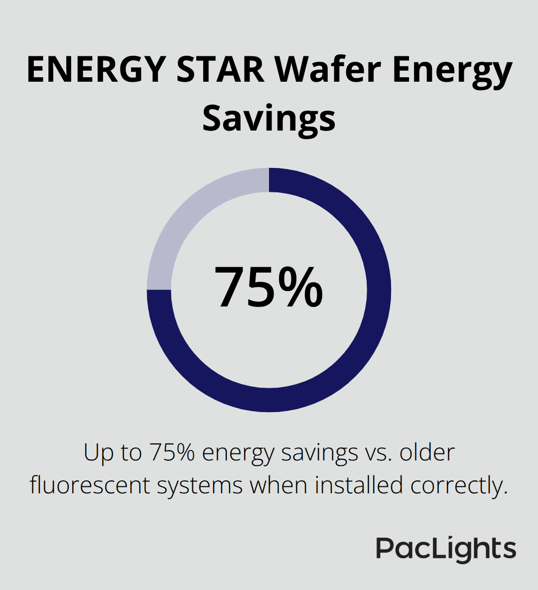
The benefits of proper wafer installation depth extend far beyond avoiding problems. Your fixtures operate at rated lumen output, maintain safe thermal performance, and distribute light evenly across your space. ENERGY STAR-certified wafers deliver up to 75% energy savings compared to older fluorescent systems, but only when installed correctly-a facility that installs wafers at the wrong depth loses this efficiency advantage and risks thermal stress that shortens fixture lifespan from 50,000 hours to just a few years.
Assess your specific space now by measuring the clearance between your structural ceiling and drop grid, identifying whether insulation sits above the grid, and calculating your grid’s load capacity. Then select wafer fixtures that match your plenum conditions and follow the installation process outlined in this guide. Contact PacLights for free lighting layout designs and ROI assessments to guide your decision and ensure your project succeeds from start to finish.
Disclaimer: PacLights is not responsible for any actions taken based on the suggestions and information provided in this article, and readers should consult local building and electrical codes for proper guidance.