

A vertical-illuminance result is useful only when the report explains what the receiving plane represents. On a sports field, a calculation point can face a spectator position, a player’s line of sight, a camera location or another project-defined direction. Rotate that plane and the same point can produce a different result even though the fixture layout has not changed.
That is why a horizontal grid summary cannot stand in for vertical performance. Before comparing reports or accepting a result, identify the plane orientation, point location and height, operating mode, modeled equipment and the criteria being checked. The goal is not to find one universal vertical value. It is to make every reported value traceable to a defined task and calculation condition.
Separate the horizontal field grid from vertical receiving planes
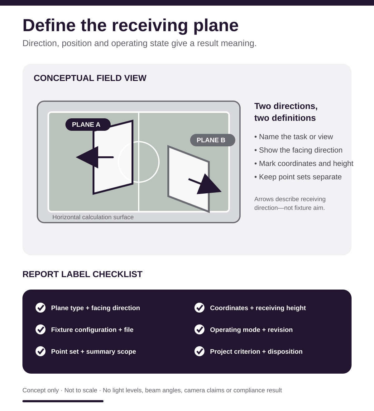
A horizontal calculation plane is typically parallel to the field surface. It can help a project team review illumination across playing areas, but it does not describe how light reaches a vertical target from a particular direction. A vertical plane is perpendicular to the field and has a directional face. Its result depends on which way that face is oriented.
Ask the report author to label each result by plane type rather than relying on column headings such as “average” or “minimum.” The report should show whether the points belong to the field surface, a vertical plane at defined locations, a boundary condition or another project-specific calculation. Summary statistics should remain attached to their original grid and plane definition.
Do not combine points from different orientations into one unlabeled table. If several viewing directions matter, the designer may report separate vertical components or separate grids. Those are not duplicates; each represents a different receiving direction. Likewise, a strong horizontal average does not demonstrate that a vertical task or viewing condition has been addressed.
Connect each plane to a task or viewing direction
The report should explain why each vertical plane faces a particular direction. A field-use review may consider visibility between participants, toward goals or along a primary direction of play. A project with video requirements may also have specified camera positions and viewing axes. Those needs come from the project criteria; they should not be invented after the calculation is complete.
Use a plan view with direction arrows or named reference points. “North-facing” may be adequate only when the site orientation and the meaning of the plane face are clear. A label such as “toward camera position C-2” is more traceable when it connects to a current drawing and coordinate. If a plane has two faces, the report should state which face receives the result or whether both directions were evaluated separately.
Keep the viewing direction distinct from fixture aiming. The sports-lighting aiming-schedule review explains how pole IDs, fixture assignments, optics and aiming references should correspond with the approved plan. A vertical receiving-plane arrow describes how a result is evaluated; it does not by itself define where any luminaire should be aimed.
Read the height, coordinates and point definitions
Every vertical result needs a location in three dimensions. The report should define the horizontal coordinates, the receiving-plane height and the reference elevation. If the field has grade changes, seating tiers or elevated viewing positions, a generic height above an undefined surface can be ambiguous. The calculation drawing and point schedule should use the same coordinate and elevation references.
Point spacing and coverage also matter. A result at a few selected positions may answer a narrow viewing question, while a larger grid may support a broader project review. Neither should be presented as though it covers the other. Record the grid extents, point spacing, excluded areas and any duplicate or coincident points. If a summary includes only a subset, identify that subset.
For a comparison between proposals or revisions, match the receiving-plane definitions before comparing statistics. If one model uses different heights, orientations or point coverage, a side-by-side table can create false precision. Ask for a rerun using the agreed definitions or keep the differences visible as unresolved assumptions.
Confirm the modeled fixture configuration
The report must also identify what generated the result. Record the luminaire family and generation, output selection, optical distribution, mounting location, mounting height, orientation, aiming reference and any accessory represented in the model. Tie each fixture to a stable pole and fixture ID rather than a count alone.
The PacLights FFHL flood-light family is offered with multiple beam choices. That illustrates why the calculation should use the photometric file for the exact proposed configuration, not a convenient file from the same family. The report package should identify the file used and show how it matches the fixture schedule and submittal.
Preserve the calculation revision and the underlying equipment schedule. If an optic, output setting, location or aiming assignment changes, issue a new result rather than overwriting the earlier record. A revision note should state what changed and which grids or vertical planes were recalculated.
State the operating mode and calculation assumptions
Sports facilities may use more than one authorized scene. A report should name the operating mode represented by each result and identify which luminaires or groups are active. If dimming is included, state the modeled setting and its documented basis. Do not mix values from full-output and reduced-output conditions in one unlabeled summary.
Other model assumptions should be visible as well: surface definitions, reflectance assumptions where used, obstructions, field geometry and the calculation software or file revision. These details do not need to overwhelm the main report, but they should be available in the calculation record. A rendering alone is not a substitute for the point data and model inputs.
When a field observation is later compared with the model, reproduce the authorized operating state and record the measurement plane, orientation, location, meter and environmental conditions. A handheld reading taken on a different plane is not a direct verification of a reported vertical value.
Keep related performance checks separate
Vertical illuminance may be one part of a larger sports-lighting review, but it should not absorb every other criterion. Horizontal illumination, uniformity, glare, spill light, color quality, flicker, camera requirements and emergency or egress conditions can involve different methods and acceptance rules. The applicable owner, designer, league, authority or media specification should identify which checks govern the project.
Do not infer camera performance from a vertical-illuminance number unless the project criteria and reporting method explicitly support that conclusion. A camera system can introduce position, direction, exposure and temporal requirements that a general field grid does not document. Likewise, a vertical average does not settle glare or uniformity questions unless the specified method defines that relationship.
The broader sports-field lighting fixture guide discusses selection and project context. The report review here is narrower: it asks whether the calculated result is labeled well enough to connect a defined receiving plane with the exact modeled system and project criteria.
Request missing definitions before accepting a comparison
A practical clarification list starts with six questions: What plane is being reported? Which direction does it face? Where are the points and at what height? Which fixtures and photometric files are modeled? Which operating mode is active? Which documented criterion is being checked? If any answer is missing, mark the result as unresolved rather than filling the gap from a screenshot or filename.
Ask for the plan view, plane labels, point schedule, equipment schedule, photometric-file references, operating-mode description, calculation revision and criteria reference as one coordinated record. The reviewer should be able to move from a summary value back to the specific points and inputs that produced it.
Close the review with a short disposition for each plane or grid: accepted as defined, revised and recalculated, or held for clarification. Preserve earlier versions and identify the change that resolved each question. That record gives facility owners, specifiers and lighting designers a defensible basis for comparing results without turning a directional calculation into a generic promise.
For a PacLights project discussion, bring the current field plan, equipment schedule, photometric report and the project’s documented performance criteria. A complete package lets the team evaluate the actual receiving planes and modeled configuration rather than guessing from an isolated summary.
Disclaimer: PacLights is not responsible for any actions taken based on the suggestions and information provided in this article, and readers should consult local building and electrical codes for proper guidance.