

A sports-lighting aiming schedule should let the project team trace every installed fixture back to the approved photometric plan. Before adjustment, match the pole and fixture IDs, exact optical assignment, mounting position, aiming reference, and drawing revision. Resolve a mismatch with the designer before treating an angle or target point as an installation instruction.
This review is useful even when every light turns on and the delivered fixture quantities are correct. Several fixtures on one pole may use different optics or point toward different parts of the field. Swapping their positions or interpreting an aiming reference differently can change the installation represented by the calculation. A successful electrical check does not establish that the lighting arrangement matches the design.
Start with one approved document set
Identify the plan issued for the work, its revision, and the associated fixture and aiming schedules. Confirm which document controls if a drawing note and a separate spreadsheet disagree. A file with a later download date is not necessarily the approved revision; retain the designer’s issue information and the project’s document-control record.
Check that the field drawing, pole arrangement, fixture quantities, and photometric report belong to that same issue. An aiming schedule prepared for an earlier pole location should not be reused simply because the pole name stayed the same. Note substitutions and approved changes explicitly, including whether a revised calculation or revised aiming information accompanies them.
The broader football lighting design calculation guide introduces layout and calculation considerations. The coordination step here comes afterward: establish which specific calculated arrangement the installation team is being asked to reproduce. Use the project’s current design criteria rather than transferring a generic light level, pole height, or uniformity target from another field.
Give every fixture an unambiguous identity
Read the pole ID and the individual fixture ID together. A row labeled only with a pole number may be insufficient when that pole supports several units. The schedule needs a clear way to distinguish their mounting positions, and that convention must agree with the drawing and field labels.
For example, a conceptual record might identify pole P-A and fixture F-03. Those labels are examples, not directions for a real project. Their value is the consistent cross-reference: the same pair should locate one fixture on the drawing, one schedule row, and one installed unit. If two units share the same label, correct the ambiguity before recording either as verified.
Also clarify the viewing direction used to describe a mounting position. “Left” and “right” can reverse when someone views a crossarm from the field instead of from behind the pole. Ask for a marked elevation or another designer-approved reference when position descriptions could be read in more than one way. Keep photographs tied to the relevant ID rather than collecting an unlabeled group of images.
Match the optic as carefully as the model
Confirm the full fixture configuration against the submittal, order information, and installed identification. Record the generation and optical option, not just a familiar family name or wattage. The optical distribution is part of the calculation input; two otherwise similar fixtures are not interchangeable merely because their housings look alike.
The current PacLights FFHL sports and flood light page lists a standard 35° beam and optional 20°, 55°, or 90° beams, as well as different mounting options. These published choices show why an aiming schedule must identify the actual selection. They do not establish that any listed option suits a particular pole, field, or proposed mounting arrangement.
Where a shield or other optical accessory is specified, include its identity and orientation in the coordination record. Ask the designer whether the calculation represents the installed accessory and configuration. If a delivered option differs, obtain a documented disposition; do not assume that moving the fixture’s aim will compensate for a different distribution.
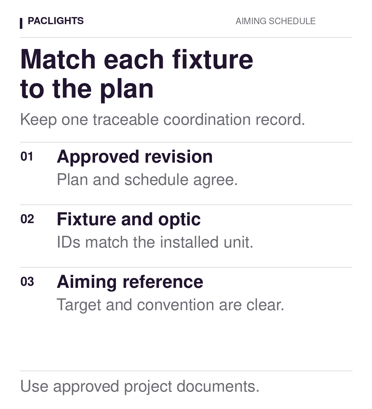
Confirm what the aiming reference means
A target point and an angle are useful only when their reference convention is understood. Ask whether the schedule uses a field coordinate, a named target, an angular setting, or a combination. Confirm the origin, reference direction, units, and relevant height or plane wherever those are needed to interpret the instruction.
Do not translate an angle from one convention to another by appearance. An elevation referenced to horizontal is different from a tilt referenced to vertical, and a direction around the pole needs a defined zero and rotation convention. The designer should resolve missing or conflicting definitions. This article intentionally provides no universal aiming angles or field-adjustment procedure.
The fixture’s markings and the project’s aiming reference may also serve different purposes. A mechanical bracket scale does not independently establish the light distribution’s orientation in a calculation. Use the exact product instructions and the designer’s documented method to connect the two. Record the source of that method so a later maintenance team can understand the original setup.
Check the mounting arrangement before adjustment
Compare the installed mounting position and arrangement with the approved documents. Record the fixture’s location on the pole or crossarm, the selected bracket, and any documented orientation requirement. Confirm that the equipment identification can be read without losing the correspondence between individual units.
Separate this document review from structural approval and installation work. A drawing correspondence check does not approve pole capacity, wind loading, fasteners, electrical connections, access equipment, or a mounting substitution. Those matters remain with the responsible project professionals and the applicable product instructions. Route discrepancies to the appropriate person instead of resolving them through an undocumented field change.
The sports-field fixture selection overview discusses distribution and aiming within the wider selection process. For this review, keep the question narrower: does each supplied and installed configuration match the one assigned to its position in the approved plan?
Use an exception log that can be closed
For each fixture, record the document reference, expected assignment, observed identity, and result. Use clear outcomes such as matched, clarification required, or not checked. Missing information is an open item; it should not become a match because the adjacent fixture was correct.
A useful discrepancy entry states the issue precisely: for example, the optic on the delivered unit differs from the schedule, the field label cannot be tied to a unique position, or the schedule omits the aiming reference convention. Attach the relevant photograph or document excerpt, identify the responsible follow-up, and retain the written disposition with its date and revision.
When an approved change affects more than one fixture, review the associated rows together. Preserve the earlier record and explain what changed. Quietly replacing values in a spreadsheet makes it difficult to distinguish an original requirement from an accepted revision or an unapproved adjustment.
Keep aiming records and acceptance evidence distinct
Close out the final fixture-to-document correspondence and retain the as-built aiming information. Record deviations, their approvals, and any remaining restrictions. A completed schedule provides traceability, but it does not by itself prove the required illuminance, uniformity, glare performance, or spill-light result.
Verify performance separately under the project’s approved acceptance method, including the specified calculation or measurement planes, operating conditions, and criteria. If a measured result differs from expectations, investigate the documented installation and design inputs before making adjustments. Preserve the connection between any approved correction and its subsequent verification.
For a PacLights project review, gather the current photometric plan, aiming and fixture schedules, full fixture configurations, mounting information, and the specific unresolved rows. That package gives the reviewer a defined question and keeps procurement, installation, and design teams working from the same arrangement.
Disclaimer: PacLights is not responsible for any actions taken based on the suggestions and information provided in this article, and readers should consult local building and electrical codes for proper guidance.